New Printer Options
We no longer sell the Markforged line of 3D printers, but we do offer the leading open source material printers from German RapRap, incredible printers from EnvisionTEC, and latest industrial printers from MakerBot. Check them out below.
Designing for 3D printing is different from designing for other types of manufacturing. In this blog post, Austin Baird, Client Technology Consultant, recounts his experience designing for 3D printing for the first time.
Since starting in a technical role with 3HTi in July 2017, my favorite aspect of work has been the wide array of software and new technologies that I get the opportunity to learn and work with. Whether it be our bread-and-butter CAD and PLM programs or cutting-edge Industrial Internet of Things (IIoT) platforms and Augmented Reality (AR), it’s exciting to work on new things every day all in the name of helping our customers from design to manufacture.
Recently I’ve taken ownership of the technical aspects of the 3D printing solutions we offer and have been having a blast. While I do love working with computers and architecting systems, it’s been refreshing to get back to my mechanical engineering roots in a very tangible and fun way. There is just something undeniably enjoyable about designing something, kicking off the print job at the end of the workday, and having it in your hands the next morning. Or, if the part is small enough, having it at the end of your lunch break!
Markforged 3D Printing Training and Markforged Mark Two 3D Printer
Today I want to talk about a design that I printed for myself on our Markforged Mark Two Desktop Series printer following my Composite Printer Training at the Markforged HQ in Boston. I’d had some fleeting experiences with 3D printing in the past: printing some parts for my senior design project, helping to post-process models from a powder-based Stratasys 3D Printer at one of my summer internships, and setting up engineers with 3D printing software at my last job as a CAD/PLM administrator. But those were nothing even remotely close to the depth of the information I’ve learned at the Markforged Composite and Metal X VAR Trainings and from working with the printers in the weeks following.
In some ways, this design felt like a culmination of the knowledge gained on designing for 3D printing from the formal training and from other resources such as Markforged’s blog. Maybe that’s a bit of an overstatement, but hey, I think this thing is sweet and I wouldn’t have been able to come up with this design a few months ago. I’m sure there will be cooler things I design in the future, but for now, I’m proud of this and I use it every day!
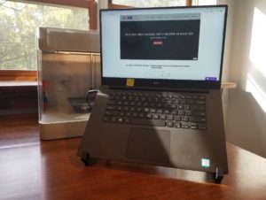
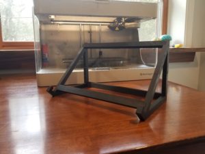
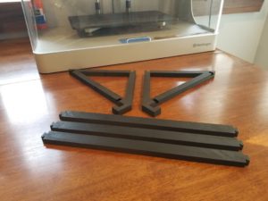
The design is a collapsible laptop stand that separates into pieces to easily pack in a bag:
Inspiration
The original inspiration to make a laptop stand occurred at Markforged. While I was at the HQ for training, a couple of Markforged engineers were happy to show me their own laptop stands printed on Markforged printers when I showed interest. One was nylon reinforced with Kevlar; the other was Onyx. With their designs, each was printed out in a single print, so obviously, a large amount of breakaway support material was necessary during the printing process. While this approach might be OK for the busy Markforged engineer who ultimately can walk downstairs and grab a spool of Onyx material fresh off the line if they wanted, I decided to think about ways to eliminate unnecessary supports to save a bit on material costs as I imagine most readers would want to. I’ll talk about how I did that and other design considerations I made along the way to design for 3D printing.
My goal was to eliminate unnecessary material supports and save on material costs by optimizing the design.
Designing for 3D Printing: Initial Sketching and Concept
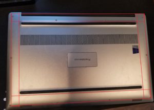
When I sat down to start designing, I started by looking at the geometry of my laptop (especially the bottom) since this is what the design would need to interface with. As I was taking measurements, I started to get an idea of where I wanted any supports that the laptop would be resting on to be located:
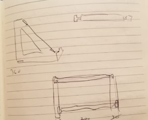
The idea of separate parts connected with interlocking joints to form the laptop stand was floating around in my head, but it was at this point that their placement and orientation started to solidify in my mind. I created this sketch, which still serves well as a crude representation of the final design:
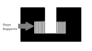
However, continuing to think about how this design would 3D print, I quickly realized the joint design that I sketched was no good since the rectangular cavities in the side pieces would require support to print even in the best orientation:
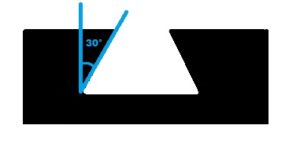
The amount of material that would be spent on these supports would be negligible. However, the supports would be hard to remove and leave a rough surface finish—not something that I wanted for my interlocking joints if I could avoid it. After turning to Google for some inspiration on joint designs, I decided that a dovetail-style joint would be perfect. Markforged printers apply support material for any overhang over 45°, so by going with something like this I could have a strong joint without having to print support material in the cavity:
Designing for 3D Printing: Using PTC Creo for CAD
Now armed with a rough idea of all aspects of the design, I got to work modeling the design in PTC Creo. After some time and several iterations (mostly slimming the design down as much as I felt I could), I ended up here:
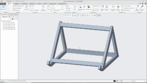
It took a few iterations to come up with the general concept of my design.
Of course, it couldn’t just be that simple. When I checked the fit of the parts on the print bed in Eiger (Markforged’s cloud-based slicing software), the side pieces were too big:
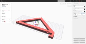
I had to split the sides into two pieces each. However, by utilizing the same dovetail joint design, this was fairly straightforward:
Designing for 3D Printing: Printing Using the Markforged Mark Two
As much as I wanted to start printing the parts right away, I didn’t know exactly what the fit of one of these joints was going to be like. And if you remember, I wanted to design the horizontal struts so they could pop out. Also, I would want a tighter fit between the sections of the side pieces as to be more permanent.
So to do my due diligence, I performed a unit test, isolating the two sections of the joint and very slightly varying the offset of the male portion to print some samples to test the fit with. I won’t delve too much into the details of performing a unit test as they do an excellent job of explaining it in the Markforged blog post. I followed the procedure, making sure to print the test pieces in the same orientation as I expected to print the final parts for more accurate results:
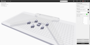
I completed a unit test with a slightly varied offset to determine exactly which offset amount would be ideal for the joints.
I printed male pieces with offsets (in mm) 0.00, -0.05, -0.10, -0.15, -0.20, and -0.25. It took a little over two hours to print everything out:
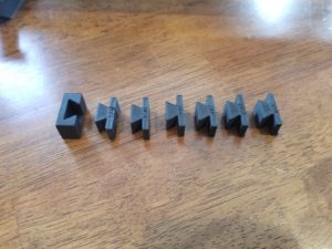
With the fit for the joints of the removable horizontal struts in mind, 0.00 was way too tight, -0.05 was a little too tight, and -0.10 was a little too loose. I split the difference and went with -0.075 as the offset that I shaved off the strut part with one final Extrude (cut) feature in Creo. For the joints joining the two pieces of a side, I decided on no offset (0.00).
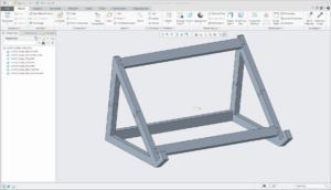
After adding rounds to most part edges normal to the print plane (rounds help reduce stress concentrations formed when the part shrinks as it cools), exporting my parts as STLs from Creo, and loading the STLs into Eiger, I could finally start printing! In the end, it took ~22 hours of print time across three print jobs.
Designing for 3D Printing: Final Thoughts
Some final thoughts:
- It is extremely impressive how light the parts are due to the automatic triangular infill structure.
- The fit for the horizontal struts is great, exactly how I wanted it.
- The fit for the side pieces is extremely tight. It was pretty tough to get them to fit together since I was connecting two joints with zero offset at the same time to form one of the sides. Those connections do seem very permanent, which is how I wanted them.
- After using the stand for a while, I probably could have slimmed down the design even further to save on some material and print time.
- The angle that the stand holds the laptop at is 45°. It’s a bit extreme; if I could redo it, I would probably go with something like 40°.
Designing for 3D printing is more than just creating a product and getting it printed. In order to create the most innovative products, engineers must design with their manufacturing processes in mind. If you are looking for consulting services for your next 3D printed design or are just looking to purchase a 3D printer, contact us.